
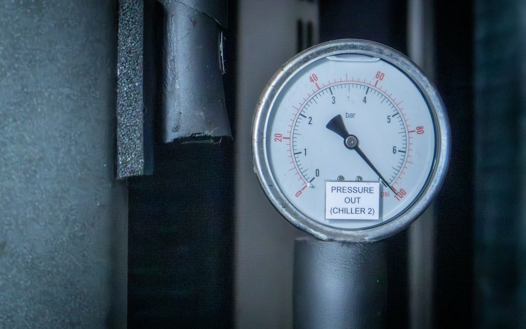
Understanding How a Boiler Pressure Relief Valve 30 PSI Works
A boiler pressure relief valve 30 psi is a safety device that opens automatically when a closed-loop hydronic heating system reaches 30 psi, discharging excess water to prevent pipe, boiler, and fitting damage. The 30 psi setting is used because residential and light commercial hot-water boilers normally operate between 12 and 24 psi, so 30 psi provides a safe buffer above normal operating pressure while remaining below the structural limits of standard boiler castings. For sizing, the valve must be rated for at least the boiler’s gross BTU output, typically handle up to 250°F, and match the boiler relief tapping size, commonly 3/4 inch. When diagnosing a 30 psi relief valve, first check the boiler pressure gauge: if pressure is below 25 psi but the valve drips, the valve seat is likely fouled or worn; if pressure is near or above 30 psi when the valve discharges, the valve is working and the cause is usually a waterlogged expansion tank, a failed pressure-reducing fill valve, or a manual fast-fill left open.
A hydronic heating system relies on hot water circulating continuously through a closed loop of pipes, baseboards, or radiant floor tubing. Because water expands when heated, the system must control that extra volume. Under normal conditions, an expansion tank absorbs the increased fluid volume. However, if a malfunction occurs—such as a component failure or excessive heating—pressure can climb rapidly.
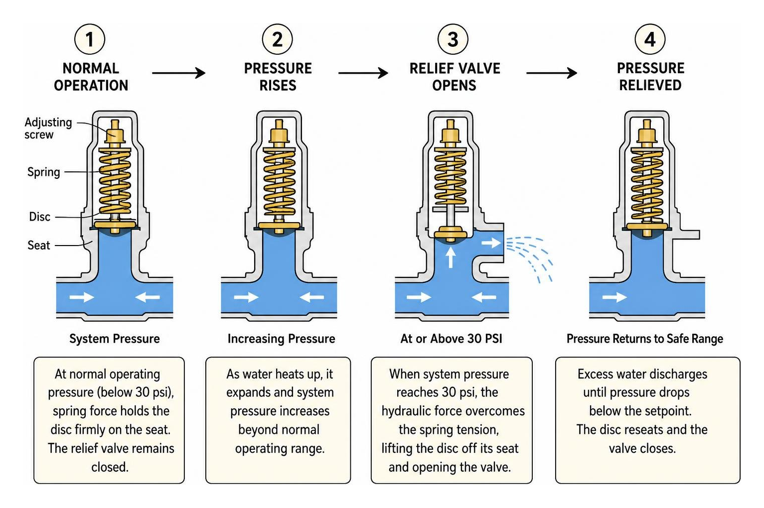
Without a safeguard, uncontrolled pressure can rupture pipes, damage the boiler heat exchanger, or compromise system fittings. This is why standard safety codes, including ASME Section IV boiler relief valve standards, mandate the installation of a dedicated safety relief device. The valve remains shut during standard operation, held in place by a heavy-duty internal spring calibrated to a specific setpoint. If system pressure reaches this threshold, the hydraulic force overcomes the spring tension, lifting the valve disc off its seat to discharge excess water safely.
Purpose of the 30 PSI Setting in Hydronic Systems
Residential and light commercial hot-water boilers are engineered as low-pressure systems. When filled with cold water, the baseline fill pressure typically sits between 12 and 15 psi. As the burner fires and brings the water up to standard operating temperatures (usually between 160°F and 180°F), thermal expansion naturally causes the pressure to rise into the 16 to 24 psi range.
A 30 psi relief rating provides a safe buffer above normal operating levels while remaining below the maximum pressure tolerance of residential boiler castings. The valve acts strictly as an emergency safety mechanism. It is a non-operating control, meaning it is not designed to regulate day-to-day pressure cycles. If a 30 psi valve opens, it signals an abnormal condition within the system that requires investigation.
Sizing Specifications for a Boiler Pressure Relief Valve 30 PSI
Choosing a replacement valve requires matching several technical parameters to your boiler:
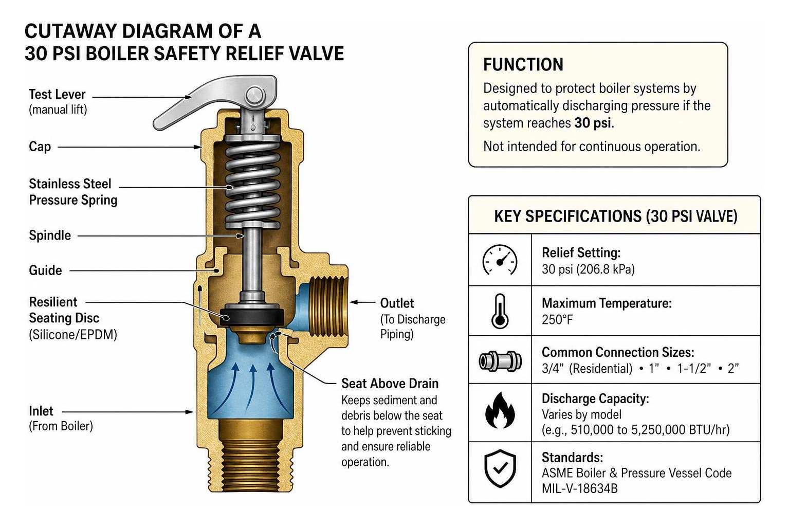
- Relief Setting: Fixed at 30 psi (206.8 kPa). These valves are factory-calibrated and non-adjustable.
- Discharge Capacity: The valve’s BTU venting capacity must equal or exceed the gross output rating of the boiler. For instance, the popular Watts 374A handles up to 550,000 BTU/hr (550K BTU), while models like the F-30 safety relief valve specifications provide compact 3/4-inch protection for standard residential configurations. Larger commercial units, such as the WAT-74030, can discharge upwards of 925,000 to over 5,000,000 BTU/hr using expanded outlets.
- Maximum Temperature: Hydronic valves must handle high water temperatures, commonly rated up to 250°F.
- Connection Sizing: Most residential boilers utilize a 22887-0030 3/4″ 30# PRESSURE RELIEF VAVLE FIP X FIP (FEMALE) connection, though larger commercial boilers require 1-inch, 1-1/2-inch, or 2-inch pipe sizes like the 174A-030 1 – Watts or the Watts 740-030 2 2 In Iron Boiler Pressure Relief Valve, 30 psi, Expanded Outlets.
- Engineering Standards: Look for valves certified under ASME Boiler and Pressure Vessel Codes and compliant with military standards such as MIL-V-18634B.
Material Specifications and Valve Engineering
Boiler relief valves are built from durable metals to withstand harsh conditions, including constant exposure to water, fluctuating temperatures, and system debris. The main body materials include cast iron, cast bronze, and forged brass.
| Valve Model & Material | Inlet / Outlet Size | Max Operating Temp | Steam / BTU Discharge Capacity | Typical Application |
|---|---|---|---|---|
| Watts 374A (Cast Iron) | 3/4″ FIP x 3/4″ FIP | 250°F | 550,000 BTU/hr | Residential hot-water space heating boilers |
| Cash Acme F-30 (All-Brass) | 3/4″ FIP x 3/4″ FIP | 250°F | 510,000 BTU/hr | Compact residential hydronic systems & storage tanks |
| Watts M335M2 (Bronze) | 3/4″ FIP x 3/4″ FIP | 250°F | 510,000 BTU/hr | Residential/light commercial hydronic loops |
| Watts 174A-030 (Bronze) | 1″ FIP x 1″ FIP | 250°F | 1,005,000 BTU/hr | High-capacity residential and light commercial boilers |
| Watts 740-030 (Cast Iron) | 2″ FIP x 2-1/2″ FIP | 250°F | 5,250,000 BTU/hr | Commercial hydronic heating systems (expanded outlet) |
Internal components are designed to resist corrosion and degradation. Most premium units feature stainless-steel pressure springs to prevent rust, alongside resilient silicone or EPDM seating discs. For standard hardware replacement needs, options like a 3/4 in. IPS 30 psi Bronze Pressure Relief Valve or other 30 PSI – Pressure Relief Valves provide durable, corrosion-resistant service.
Seat-Above-Drain and Anti-Sticking Designs
One issue with hydronic systems is the accumulation of sediment, magnetite (black iron oxide), and mineral scale. Over time, heavy particulate can settle around valve seats, causing them to jam, weep, or fail to open.
To prevent this, advanced valves incorporate a “seat-above-drain” layout. By elevating the valve seat above the lowest drainage line, gravity draws particulate away from the sealing disc rather than letting it pool around the elastomer seal.
Additionally, designs like those found in the Watts 335M2, 3/4” Boiler Pressure Relief Valve utilize non-mechanical disc-to-seat alignment, often pairing high-heat silicone discs with Teflon-coated metal seats. This prevents the rubber disc from bonding, sticking, or freezing to the metal orifice during long stretches of inactivity between heating seasons.
Difference Between Boiler Relief Valves and Water Heater T&P Valves
Homeowners frequently confuse closed-loop boiler relief valves with domestic water heater temperature and pressure (T&P) relief valves. While both are critical safety components, they serve different systems and are not interchangeable:
- Pressure-Only vs. Temperature & Pressure: Boiler safety valves are designed solely to monitor fluid pressure (opening at 30 psi). Residential domestic water heater T&P valves are calibrated to open at 150 psi or when water reaches 210°F, using a extended thermal probe inserted into the tank.
- Potable Water Compliance: Most cast-iron and standard bronze boiler valves are engineered for non-potable heating loops and do not meet low-lead drinking water standards.
- Operating Thresholds: Installing a 150 psi water heater valve on a hydronic boiler will leave the boiler completely unprotected against 30-50 psi structural failures. Conversely, putting a 30 psi boiler valve on a 60 psi municipal domestic water heater will cause the valve to discharge constantly.
If you are dealing with a standard domestic hot water system rather than a heating boiler, understanding water heater pressure relief valve leaking causes can help you address issues with 150 psi domestic valves.
Diagnostic Steps for Boiler Pressure Relief Valve 30 PSI Issues
A dripping, weeping, or discharging pressure relief valve requires prompt attention. However, a discharging valve is often responding correctly to an overpressure condition elsewhere in the system, rather than being broken itself.
To diagnose the problem, check the boiler’s pressure-temperature gauge (tridicator):
- Scenario A: Gauge reads below 25 psi, but the valve drips. The valve seat has likely failed due to mineral buildup, sediment fouling, or spring fatigue.
- Scenario B: Gauge reads near or above 30 psi when the valve discharges. The relief valve is functioning properly as a safety device. The issue is an external system component causing excessive pressure.
Knowing how to fix a leaking pressure relief valve in simple steps can help you determine whether the issue is a simple seating problem or a sign of higher system pressure.
Troubleshooting Failure Signs in a Boiler Pressure Relief Valve 30 PSI
If the boiler gauge indicates normal pressure (12–18 psi), inspect the valve for the following physical symptoms:
- Mineral Crust and Scaling: White, chalky deposits around the outlet port indicate long-term minor weeping. Minerals dry and crystallize, preventing the disc from creating a watertight seal.
- Corrosion on the Spring Housing: Heavy green oxidation (on bronze) or rust scale (on iron) around the bonnet indicates internal seal breakdown, which can compromise the spring mechanism.
- Persistent Drips After Testing: Manually lifting the test lever on an older valve can dislodge rust flakes that settle on the seat, preventing it from fully closing.
Reviewing why pressure relief valves drip provides helpful insight into diagnosing mechanical seal degradation versus pressure-related discharge.
Diagnosing External Causes of High System Pressure
When the valve discharges and the gauge confirms pressure is spiking to 30 psi or higher, systematically check these three external components:
- Waterlogged Expansion Tank: Hydronic heating systems rely on an expansion tank with an internal rubber bladder separating system water from a pressurized air cushion (pre-charged to 12–15 psi). If the bladder tears or loses its air charge, the tank fills with water. Because water does not compress, thermal expansion has nowhere to go, causing system pressure to spike from 12 psi to 30 psi whenever the burners ignite.
- Failed Automatic Pressure-Reducing Fill Valve (PRV): The automatic water feeder connects your home’s domestic water supply (typically 50–70 psi) to the boiler loop, dropping it to a steady 12–15 psi cold-fill pressure. If internal scale or debris prevents this valve from closing tightly, domestic water will slowly seep into the boiler loop until the pressure reaches 30 psi, triggering the relief valve.
- Manual Bypass or Fast-Fill Left Open: During maintenance or zone purging, technicians use a fast-fill lever to introduce 20–25 psi to push out air pockets. If this bypass lever is accidentally left cracked open, system pressure will quickly climb to 30 psi.
Proper Installation, Testing, and Replacement Best Practices
Installing a boiler pressure relief valve requires attention to pipe orientation and drainage to ensure it operates safely when needed.
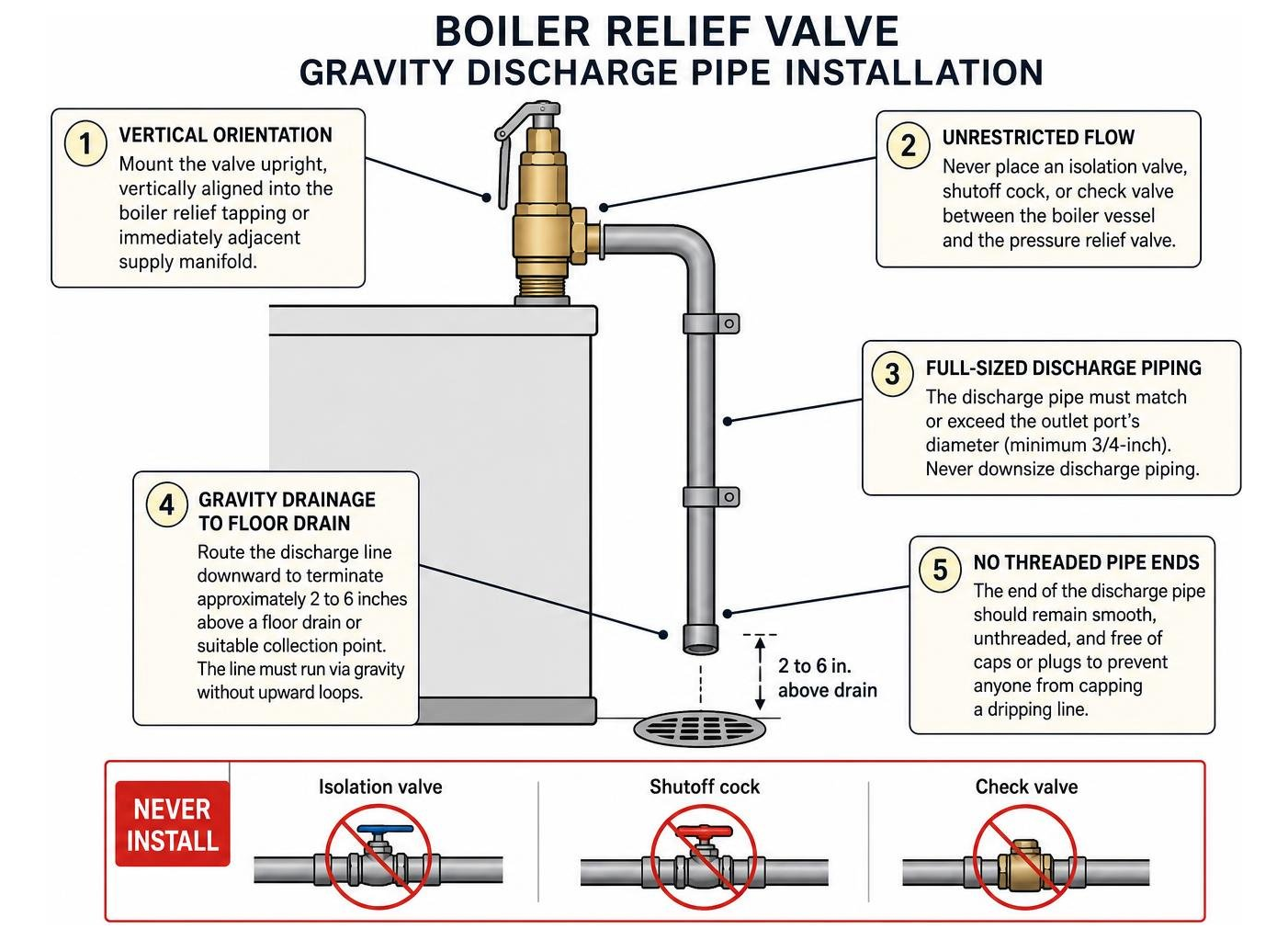
- Vertical Orientation: Mount the valve upright, vertically aligned into the designated boiler relief tapping or immediately adjacent supply manifold. Never install a valve horizontally or inverted, as gravity can cause sediment to accumulate against the disc.
- Unrestricted Flow: Never place an isolation valve, shutoff cock, or check valve between the boiler vessel and the pressure relief valve.
- Full-Sized Discharge Piping: The discharge pipe running from the valve outlet must match or exceed the outlet port’s diameter (minimum 3/4-inch). Never downsize or reduce discharge piping.
- Gravity Drainage to Floor Drain: Route the discharge line downward to terminate approximately 2 to 6 inches above a floor drain or suitable collection point. The line must run via gravity without upward loops that could trap water.
- No Threaded Pipe Ends: The end of the discharge pipe should remain smooth, unthreaded, and free of caps or plugs to prevent anyone from capping a dripping line.
Step-by-Step Valve Replacement Guidelines
If you need to replace a damaged valve or are following an expert walkthrough like the How to Replace a Boiler Pressure Relief Valve – Expert Q&A, follow these general steps:
- Power Down and Cool: Shut off the electrical power to the boiler and close the main fuel supply. Allow the system water to cool below 100°F to prevent thermal shock and burn risks.
- Isolate and Depressurize: Close the cold-water feed line and isolate the boiler using supply and return isolation valves. Attach a hose to the boiler drain valve and drain sufficient water until the tridicator gauge reads 0 psi.
- Remove the Old Valve: Use two pipe wrenches—one to brace the boiler manifold fitting and the other to back the valve out counterclockwise.
- Prepare the Threads: Clean the male pipe threads thoroughly with a wire brush to remove old compound. Apply high-temperature PTFE pipe thread tape, followed by an approved pipe thread sealant paste.
- Install the New Valve: Thread the replacement 30 psi valve clockwise into the fitting hand-tight, then complete the seal using your pipe wrench until snug and oriented correctly. Avoid overtightening into cast fittings.
- Reinstall the Discharge Line: Reconnect the discharge piping, verifying it maintains a continuous downward slope to the floor.
- Refill and Purge: Reopen the cold-water supply to re-establish the 12–15 psi cold-fill baseline. Purge any trapped air pockets through the zone bleeder valves, inspect for leaks, and restore power.
Routine Maintenance and Manual Lever Testing
Relief valves should undergo visual checks and routine testing to ensure the internal assembly does not seize:
- Visual Check (Monthly during heating season): Inspect the outlet pipe for signs of moisture, mineral scale, or active dripping.
- Manual Lever Test (Annually): Place a bucket beneath the discharge pipe. With the boiler operating under normal pressure and temperature, lift the manual test lever fully for 2 to 3 seconds, then release it smoothly. A brief burst of water should discharge freely into the bucket, and the valve should snap shut cleanly.
- Post-Discharge Inspection: If the valve continues to drip after a manual test, raise the lever briefly once or twice more to flush any loose sediment off the seat. If weeping persists, the internal seal has reached the end of its service life and should be replaced.
Frequently Asked Questions About 30 PSI Boiler Relief Valves
Can I install a 30 psi pressure-only relief valve on a domestic potable water heater?
No. Domestic water heaters operate on open, potable municipal water systems at pressures ranging from 40 to 80 psi and require combination Temperature and Pressure (T&P) relief valves rated for 150 psi and 210°F. Installing a 30 psi valve on a domestic water heater will cause the valve to discharge immediately upon filling. Additionally, non-potable boiler valves are not certified to lead-free plumbing standards.
Why does my boiler pressure gauge spike near 30 psi only when the burners fire?
When pressure is normal (12–15 psi) while the system is resting but climbs toward 30 psi whenever the burners run, the issue is almost always a waterlogged expansion tank. As the heating loop warms up, the expanding water has no compressible air cushion to absorb it, driving system pressure up to the relief threshold.
Does a 30 psi relief valve always need replacement after it blows off?
Not always, but it is a good idea to monitor it closely. When a relief valve opens under high pressure, high-velocity water can carry pipe scale across the seat, which can score the rubber disc or get trapped under the seal. If the valve reseats cleanly and stops dripping once system pressure returns to 12–15 psi, it can remain in service. However, if it continues to weep after the pressure drops, the valve should be replaced.
Conclusion: Ensuring Safe and Reliable Hydronic Heating
A 30 psi boiler pressure relief valve plays an essential role in protecting closed-loop hydronic systems from dangerous overpressurization. Whether you are dealing with an aging valve, a failing expansion tank bladder, or an overfilling feed line, addressing the issue promptly helps protect your equipment and keeps your heating system running efficiently.
For homeowners troubleshooting pressure leaks across other home systems, reviewing how to address a weeping pressure relief valve offers useful context for maintaining these safety devices.
If your boiler’s relief valve is dripping, popping open, or overdue for a maintenance check, the team at Honest Home Services is here to help. We provide hydronic heating diagnostics, boiler maintenance, and emergency service throughout Salt Lake City, Salt Lake County, Davis County, and surrounding communities—including Layton, Bountiful, Draper, and Park City. Contact us today to schedule an inspection with a local technician.